Connectors
There’s a handful of connectors on the Dell Wyse 3020 board.
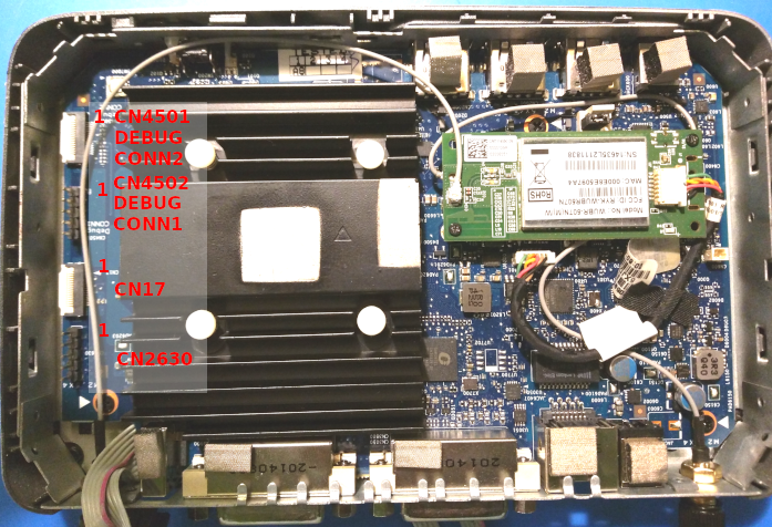
The UART1 serial port can be easily accessed via 0.1” pitch pin header on CN4502. UART3 and UART4 could possibly be accessed by connecting a 0.05” pich 16-pin flat cable to CN17 but the pin controller needs to be told to route the UART functions there (it defaults to GPIO). Probably not worth it.
JTAG can be accessed via CN4501.
Some of the pins have not been identified, but there can hardly be anything too useful.
CN4501
Connector near the front. Pin 1 also faces front of the machine. Marked on the PCB as follows:
CN4501
DEBUG
CONN2
| Pin Number | Function |
|---|---|
| 1 | GPIO_52 |
| 2 | GPIO_51 |
| 3 | GND |
| 4 | |
| 5 | JTAG_TDI |
| 6 | JTAG_TMS |
| 7 | JTAG_TCK |
| 8 | JTAG_TCK |
| 9 | JTAG_TDO |
| 10 | RESET# |
| 11 | GND |
| 12 | |
| 13 | |
| 14 | +3V |
| 15 | GPIO_64 |
| 16 |
CN4502
Pin 1 faces front of the machine. Marked on the PCB as follows:
CN4502
DEBUG
CONN1
| Pin Number | Function |
|---|---|
| 1 | |
| 2 | GPIO_69 |
| 3 | GND |
| 4 | UART1_RX |
| 5 | UART1_TX |
CN17
Pin 1 faces front of the machine.
| Pin Number | Function |
|---|---|
| 1 | GPIO_115 |
| 2 | GPIO_116 |
| 3 | |
| 4 | GPIO_117 |
| 5 | GPIO_118 |
| 6 | GPIO_119 |
| 7 | GPIO_120 |
| 8 | GPIO_121 |
| 9 | GPIO_122 |
| 10 | |
| 11 | |
| 12 | |
| 13 | |
| 14 | |
| 15 | |
| 16 |